| 2.2 Flow Measurement |
| 2.2 Flow Measurement |
Flow measurement is critical to determine the amount of material purchased and sold, and in these applications, very accurate flow measurement is required. In addition, flows throughout the process should the regulated near their desired values with small variability; in these applications, good reproducibility is usually sufficient. Flowing systems require energy, typically provided by pumps and compressors, to produce a pressure difference as the driving force, and flow sensors should introduce a small flow resistance, increasing the process energy consumption as little as possible. Most flow sensors require straight sections of piping before and after the sensor; this requirement places restrictions on acceptable process designs, which can be partially compensated by straightening vanes placed in the piping. The sensors discussed in this subsection are for clean fluids flowing in a pipe; special considerations are required for concentrated slurries, flow in an open conduit, and other process situations.
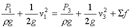
Several sensors rely on the pressure drop or head occurring as a fluid flows by a resistance; an example is given in Figure 1. The relationship between flow rate and pressure difference is determined by the Bernoulli equation, assuming that changes in elevation, work and heat transfer are negligible.
Figure 1. Orifice flow meter
|
|
|
(2) |
|
|
|
|
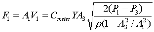
The meter coefficient, Cmeter, accounts for all non-idealities, including friction losses, and depends on the type of meter, the ratio of cross sectional areas and the Reynolds number. The compressibility factor, Y, accounts for the expansion of compressible gases; it is 1.0 for incompressible fluids. These two factors can be estimated from correlations (ASME, 1959; Janna, 1993) or can be determined through calibration. Equation (3) is used for designing head flow meters for specific plant operating conditions.
When the process is operating, the meter parameters are fixed, and the pressure difference is measured. Then, the flow can be calculated from the meter equation, using the appropriate values for Cmeter and Y. All constants are combined, leading to the following relationship.
|
|
|
|
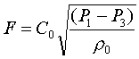
In the usual situation in which only reproducibility is required, the fluid density is not measured and is assumed constant; the simplified calculation is where the density is assumed to be its design value of ro. This is a good assumption for liquid and can provide acceptable accuracy for gases in some situations. Again, all constants can be combined (including ro) into C1 to give the following relationship.
|
relationship for installed head meter with constant density |
|
|
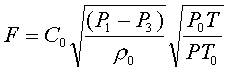
If the density of a gas varies significantly because of variation in temperature and pressure (but not average molecular weight), correction is usually based on the ideal gas law using low cost sensors to measure T and P according to
|
relationship for installed head meter, gas with constant MW, changing T and P |
|
|
where the density (assumed constant at ro), temperature (To) and pressure (Po) were the base case values used in determining Co. If the density varies significantly due to composition changes and high accuracy is required, the real-time value of fluid density (r) can be measured by an on-stream analyzer for use as ro in equation (4) (Clevett, 1985).
The flow is determined from equation (5) by taking the square root of the measured pressure difference, which can be measured by many methods. A U-tube manometer provides an excellent visual display for laboratory experiments but is not typically used industrially. For industrial practice a diaphragm is used for measuring the pressure drop; a diaphragm with one pressure on each side will deform according to the pressure difference.
Note that the pressure in the pipe increases after the vena contracta where the flow cross section returns to its original value, but because of the meter resistance, the pressure downstream of the meter (P3) is lower than upstream pressure (P1). This is the “non-recoverable” pressure drop of the meter that requires energy, e.g., compressor work, to overcome and increases the cost of plant operation. The non-recoverable pressure losses for three important head meters are given in Figure 5.
The low pressure at the point of highest velocity creates the possibility for the liquid to partially vaporize; it might remain partially vaporized after the sensor (called flashing) or it might return to a liquid as the pressure increases after the lowest pressure point (called cavitation). We want to avoid any vaporization to ensure proper sensor operation and to retain the relationship between pressure difference and flow. Vaporization can be prevented by maintaining the inlet pressure sufficiently high and the inlet temperature sufficiently low.
Some typical head meters are described briefly in the following.
Orifice: An orifice plate is a restriction with an opening smaller than the pipe diameter which is inserted in the pipe; the typical orifice plate has a concentric, sharp edged opening, as shown in Figure 1. Because of the smaller area the fluid velocity increases, causing a corresponding decrease in pressure. The flow rate can be calculated from the measured pressure drop across the orifice plate, P1-P3. The orifice plate is the most commonly used flow sensor, but it creates a rather large non-recoverable pressure due to the turbulence around the plate, leading to high energy consumption (Foust, 1981).
Venturi Tube: The venturi tube shown in Figure 2 is similar to an orifice meter, but it is designed to nearly eliminate boundary layer separation, and thus form drag. The change in cross-sectional area in the venturi tube causes a pressure change between the convergent section and the throat, and the flow rate can be determined from this pressure drop. Although more expensive that an orifice plate; the venturi tube introduces substantially lower non-recoverable pressure drops (Foust, 1981).
Figure 2. Venturi flow meter
Flow
Nozzle: A flow nozzle consists of a
restriction with an elliptical contour approach section that terminates
in a cylindrical throat section. Pressure drop between the locations
one pipe diameter upstream and one-half pipe diameter downstream is
measured. Flow nozzles provide an intermediate pressure drop
between orifice plates and venturi tubes; also, they are applicable to
some slurry systems.
Elbow meter: A differential pressure exists when a flowing fluid changes direction due to a pipe turn or elbow, as shown in Figure 3 below. The pressure difference results from the centrifugal force. Since pipe elbows exist in plants, the cost for these meters is very low. However, the accuracy is very poor; there are only applied when reproducibility is sufficient and other flow measurements would be very costly.
Figure 3. Elbow flow meter.
Pitot tube and annubar: The pitot tube,
shown in Figure 4 below, measures the static and dynamic pressures of
the fluid at one point in the pipe. The
flow rate can be determined from the difference between the static and
dynamic pressures which is the velocity head of the fluid
flow. An annubar consists of several pitot tubes placed
across a pipe to provide an approximation to the velocity
profile, and the total flow can be determined based on the
multiple measurements. Both the pitot tube and annubar
contribute very small pressure drops, but they are not physically
strong and should be used only with clean fluids.
Figure 4.
Pitot flow meter.
Figure 5. Flow meter non-recoverable
pressure losses (Andrews and Williams, Vol 1, 1979)
The following flow sensors are based on physical principles other than
head.
Turbine: As fluid flows through the turbine, it causes the turbine to rotate with an angular velocity that is proportional to the fluid flow rate. The frequency of rotation can be measured and used to determine flow. This sensor should not be used for slurries or systems experiencing large, rapid flow or pressure variation.
Vortex shedding : Fluid vortices are formed against the body introduced in the pipe. These vortices are produced from the downstream face in a oscillatory manner. The shedding is sensed using a thermistor and the frequency of shedding is proportional to volumetric flow rate.
Positive displacement: In these sensors, the fluid is separated into individual volumetric elements and the number of elements per unit time are measured. These sensors provide high accuracy over a large range. An example is a wet test meter.
For an excellent concise discussion on flow sensors (including many not discussed here), select this button to be directed to a site on the WWW. |
|
For additional information on variable area (e.g., rotometer) flow sensors, select this button to be directed to a site in the WWW. |
|
For additional information on orific plate flow sensors, select this button to be directed to a site in the WWW. |
|
For additional information on venturi flow sensors, select this button to be directed to a site in the WWW. |
|
For additional information on pitot tube flow sensors, select this button to be directed to a site in the WWW. |
|
For additional information on magnetic/vortex/ultrasonic flow sensors, select this button to be directed to a site in the WWW. |
|
For additional information on coriolis flow sensors, select these two buttons to be directed to a site in the WWW. |
|
Table 2. Summary of flow sensors
| Sensor | Rangeability1 | Accuracy2 | Dynamics (s) | Advantages | Disadvantages |
| orifice | 3.5:1 | 2-4% of full span | - |
-low cost -extensive industrial practice |
-high pressure loss -plugging with slurries |
| venturi | 3.5:1 | 1% of full span | - |
-lower pressure loss than orifice -slurries do not plug |
-high cost -line under 15 cm |
| flow nozzle | 3.5:1 | 2% full span | - |
-good for slurry service -intermediate pressure loss |
-higher cost than orifice plate -limited pipe sizes |
| elbow meter | 3:1 | 5-10% of full span | - | -low pressure loss | -very poor accuracy |
| annubar | 3:1 | 0.5-1.5% of full span | - |
-low pressure loss -large pipe diameters |
-poor performance with dirty or sticky fluids |
| turbine | 20:1 | 0.25% of measurement | - |
-wide rangeability -good accuracy |
-high cost -strainer needed, especially for slurries |
| vortex shedding | 10:1 | 1% of measurement | - |
-wide rangeability -insensitive to variations in density, temperature, pressure, and viscosity |
-expensive |
| positive displacement | 10:1 or greater | 0.5% of measurement | - |
-high reangeability -good accuracy |
-high pressure drop -damaged by flow surge or solids |
Notes: