| 3.7 Valve Installation |
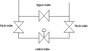
Many important factors must be considered when designing the physical installation of the control valve. Perhaps the most important is the design of piping for manual bypass. A control valve may require periodic maintenance to correct leaks, noise, vibration, increasing deadband, and so forth. Since a plant shutdown usually involves a large economic penalty, an incentive exists to maintain plant operation while the control valve is being repaired in many, but not all, situations. The bypass system shown in Figure 11 provides the ability to “block” out the control valve while the process flow passes through the manual bypass valve. The performance is best when the design includes 10-20 diameters of straight run piping in the inlet and 3-5 diameters in the outlet. An operator must close the block valves and manipulate the bypass valve to achieve some desired operating condition, such as flow rate or temperature. For a typical globe valve, the valve should be installed so that the stem moves vertically with the actuator above the valve. In addition, the valve should be located with enough clearance from other equipment so that maintenance can be performed on the valve.

Figure 11. Typical control valve installation
Control valves are used to affect the flow rate in a pipe, i.e., they are used to throttle flow. Control valves do not provide reliable, tight closure, so that some small flow rate can be expected when the valve is "fully closed". The amount of leakage depends upon the valve body and the fluid.
| For a brief discussion of bypass select and piping details, select the button. |
| For a brief discussion of valve leakage, select this button to be directed to a site on the WWW. |